A 200mW radio beacon for CW, QRSS and WSPR digital modulations.
A description of my multimode radio beacon for HF data transmissions. This beacon is simple to build with readily available and cheap components. It is a TX-only device and does not require other external radio equipment. Its applications are real-time HF propagation monitoring and antenna performance evaluation.
The project material is available in its github repository! There you can find the source code, hardware schematics and additional notes on hardware and software configuration.
Specifications
- TX in any amateur band between 160m to 10m (1.5 to 28 MHz).
- Filtered RF output of up to 200 mW.
- Programmable in Cpp with custom messages and TX duty cycle.
- Internal STM32 RTC synchronized to GPS network time for WSPR operation.
Overview
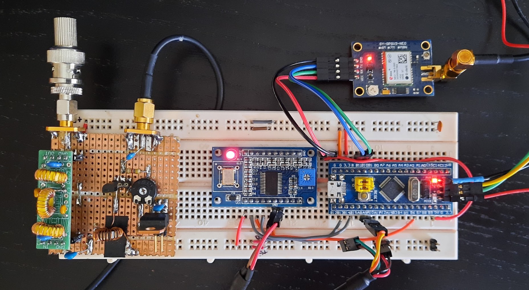
Hardware
The main hardware blocks are commercial-off-the-shelve units, readily available in most electronics suppliers. The only excception is the power amplifier, which is described in greater detail later on.
- STM32 “Blue pill”: is the controller board mounting a STM32 microcontroller with the minimal circuitry for it to function. It also carries the crystal needed by the internal RTC. Powered at 5 Volts.
- GPS: is an external GPS module that can provide NMEA strings through a serial interface to the STM32 controller. It provides time and position information. Powered through the +5V Voltage domain in the blue pill.
- AD9850 DDS oscillator: generates the FSK or CW modulated signal in the required frequency as controlled by the STM32. Powered through the +5V Voltage domain in the blue pill.
- Power amplifier: provides a gain of 5dB to the oscillator output signal. It is powered at 12 Volts from an external supply and presents a 50 ohms output impedance.
- Output filter: Low pass filters that eliminates undesired harmonics from the power amplifier output. Presents a 50 ohms input and output impedance.
Interfaces
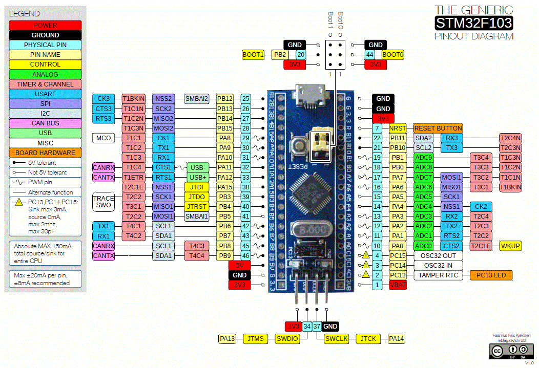
The interfaces used between the STM32 controller and the peripherals are listed below. An overview of the STM 32 IO capabitilies can be found in this pinout diagram (link).
- SPI master
2, 5 Volts tolerant, is used to load the target frequency in the DDS. - Serial TTL
Serial1, 5 Volts tolerant, is used to interface with the development PC, connected through a USB/Serial TTL adapter. - Serial TTL
Serial3, 5 Volts tolerant, is used to interface with the GPS. - ST-Link dongle for programming and development connected through USB to the development PC.
Power amplifier and output filter stages
The final stage is composed of a power amplifier and a filter to elimiante output harmnonics an overview is shown in the schematic below.
The amplifier is build around Q1, a single BS170, a general purpose N-Channel FET (link to datasheet). U1 regulates the input to the bias network to 5 Volts, which is to adjust the bias through RV1. C1 filters noise in the supply line. Capacitors C2 and C3 are used to block the DC levels from input and output signals. L1 is a FT37-43 toroid with 25 turns of 0.40mm diamater copper wire. The inductor prevents the amplified HF signal to affect the supply line Vcc and it is critical for the correct operation of the amplifier.
The bias point is adjusted through RV1 to produce 200 mW output (23 dBm) when driven from a 18 dBm input signal and terminated at 50 ohms.
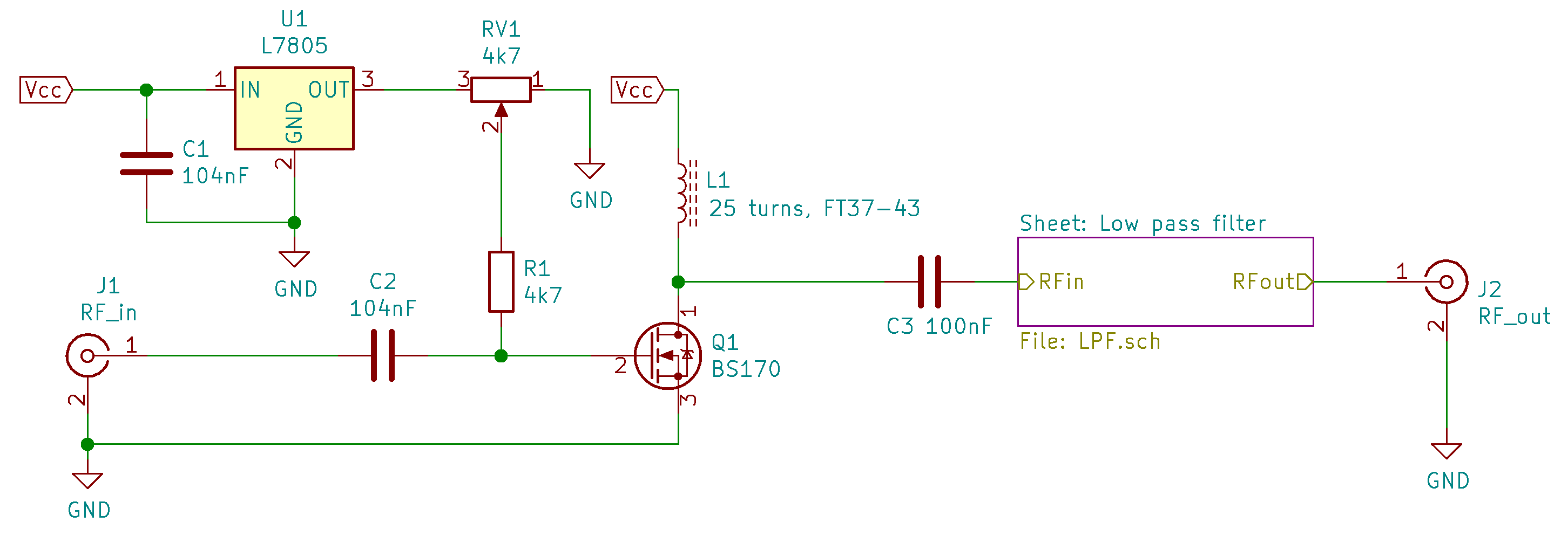
The power amplifier is connected to the VOUTP output from the AD9850 module. This is an unfiltered, square, 5 Volts output that can drive the 50 ohms impedance presented by the low pass filter. It is important to use this specific output and not the IOUT output from the breakout board, since the amplitude of the latter is approximately 200 mV and it is fitered and unnecesarily terminated at 200 ohms (this is probably a missinterpretation of the AD9850 datasheet by the carrier board producer).
When measuring the output of the amplifier, it is important to terminate it properly at 50 ohms to achieve correct readings. In higher power amplifiers it is also a must, to avoid damages due to high SWR (not an issue here, since the maximum power is 200 mW).
The filter stage is a Low Pass filter kit from QRPlabs. It is a simple 7-element passive filter design available for different bands. Alternatives to this design can be found in most RF handbooks (with pre-calculated value tables).
Software
The control software is written in Cpp and uses the STM32duino abstraction layer. The software is structured in the following classes:
- Beacon: is the entry point implementing the initial setup and the periodic loop behaviour.
- QRSS: is a base class contining the common operations for QRSS operation: message transmission, morse encoding and access to the oscillator wrapper.
- FSK Sender and CW Sender: are subclasses of QRSS that implement Frequency Shift Keying CW and traditional morse code respectively.
- WSPR: implements the WSPR encoding using its four-level FSK encoding.
- TimeSync: maintains a local notion of time synchronized to the GPS network. The STM32 internal RTC is synchronized to the time values provided by the GPS through NMEA strings. Triggers the transmission when scheduled through RTC alarm attached interrupt.
The control software uses the following third-party open-source libraries:
- AD8850: controls the DDS oscillator. Based on the library from R. Tilard, modified to: use a configurable SPI interface and added a calibration method.
- TinyGPSPlus: interfaces the GPS and parses the NMEA strings. The library contains methods for positioning and navigation however, only time functionality is used. Library from Mikal Hart.
Entry point and main loop
The entry point to the controller software is in the beacon.ino file and following the arduino sketch convention it is structured in two functions: setup and loop. The function setup initializes the system by:
- Setting up the hardware.
- Constructing the classes that will be used during execution.
- Syncrhonizing the STM32 microcontroller RTC to the GPS network time.
- Scheduling the first transmission, to take place in the next slot available.
The scheduling of the first transmission is done through the function scheduleNextWSPRTX, which takes as parameters the callback function to be invoked when the time SCHEDULE_FOR_NEXT_SLOT has elapsed: the function beaconTX().
void setup() {
    // ...
    gps = new TinyGPSPlus();
    rt = new RTClock(RTCSEL_LSE);

    timeKeeper = new TimeSync(rt, gps);
    timeKeeper->syncRTC();
    timeKeeper->scheduleNextWSPRTX(beaconTX, SCHEDULE_FOR_NEXT_SLOT);
    // ...
}

void beaconTX() { // Invoked from an ISR context
    TX_triggered = true;
}
The function loop waits for a TX_trigger event to be signaled in order to start the wspr message transmission. Once that transmission is finished the next transmission is scheduled to take place at the regular SCHEDULE_TX_PERIODIC time has elapsed.
void loop() {
    if (TX_triggered) {
        BEACON_SERIAL.println("Beacon sending WSPR frame");
        wsprSender->sendWSPRmessage();
        timeKeeper->scheduleNextWSPRTX(beaconTX, SCHEDULE_TX_PERIODIC);
        TX_triggered = false;
    }
}
QRSS and CW encoding
The plain text to morse code symbol translation is implemented by a look-up function, which returns an uint8_t representing the sequence of DOTs and DASHes by using 0s and 1s respectively. When transmitting the letter the uint8_t is shifted until all the symbols have been sent by using the dot(), and dash() function. For plain QRSS and CW these functions key directly the oscillator during a certain time. The look-up function and the symbol encoding using uint8_t is inspired by the QRSS sketch from Hans Summers in Ham radio for Arduino and Picaxe. The function below shows how a dash is sent, the oscillator is set at a defined frequency for a period of time defined by DOT_CW * DASH_WEIGHT. Finally, an intersymbol delay is inserted.
void CW_SENDER::dash() {
    _oscillator->setFrequency(_baseFrequency);
    delay(DOT_CW * DASH_WEIGHT);
    _oscillator->setFrequency(0);
    delay(CW_DELAY); // pause after symbol set to one dot duration
}
QRSS-FSK encoding
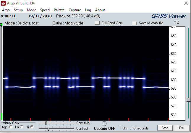
QRSS-FSK is a variation of “time-based” QRSS, where two signals at two different frequencies are used to represent keying or abscence of it. This is exemplified below, where a transmission of the letters C (dash - dot - dash - dot) and Q (dash - dash - dot - dash) can be seen. This is accomplished by using a base frequency at 590 Hz to represent no keying and a shift of 10 Hz on top to represent keying.
The message transmission logic and text to morse code translation is reused by subclassing the class QRSS. The only extension needed to enable QRSS-FSK is to implement the functions dash() and dot() using the frequency shift. The code snippet below shows how this is conducted for the dash() function.
void FSK_SENDER::dash() {
    _oscillator->setFrequency(_baseFrequency + FSK_HIGH);
    delay(QRSS_DOT * QRSS_WEIGHT);
    _oscillator->setFrequency(_baseFrequency);
    delay(QRSS_DELAY);
}
WSPR encoding
WSPR is a digital mode using a 4-symbol Frequency Shift Keying modulation. The predefined separation between the tones representing the symbols is 1.4648 Hz. A WSPR message is composed of 162 symbols and it takes 110.6 s to transmit. The baudrate is 1.4648 bits/s. The standard WSPR message contains: “callsign + 4-digit Maidenhead locator + power in dBm”. Additional information on the protocol can be found in Appendix B of the WSPR user manual.
The beacon stores the message to be transmitted in a uint8_t array. This message is hardcoded in the beacon sourcecode. See below and excerpt of the test message provided in the WSPR user manual, containing the sequence of tones that have to be generated to send the messate “K1ABC FN42 37”.
uint8_t EXAMPLE_WSPR_DATA[] = { // Channel symbols for the message "K1ABC FN42 37"
    3, 3, 0, 0, 2, 0, 0, 0, 1, 0, 2, 0, 1, 3, 1, 2, 2, 2, 1, 0, 0, 3, 2, 3,
    1, 3, 3, 2, 2, 0, 2, 0, 0, 0, 3, 2, 0, 1, 2, 3, 2, 2, 0, 0, 2, 2, 3, 2,
    ...
};
Individual tones to generate the symbols are generated by the generateTone(uint8_t t) function. The function takes the _baseFrequency in which the beacon is going to transmit and adds the required separation to generate the needed tone. Finally the oscillator is driven at the computed frequency.
void WSPR::generateTone(uint8_t t) {
    uint32_t tone = _baseFrequency + (t)*WSPR_TONE_SEPARATION;
    // The actual frequencies for each tone will be:
    //     (_baseFrequency + [0, 1, 3, 4])
    // this is due to the rounding of frequency after the tone calculation.
    _oscillator->setFrequency(tone);
}
To send the complete WSPR message the function sendWSPRmessage() goes through the array containing the message MY_WSPR_DATA and generates the needed tone. A delay WSPR_INTERSYMBOL_DELAY is inserted between each symbol.
void WSPR::sendWSPRmessage() {
    for (uint8_t i = 0; i < WSPR_MESSAGE_LENGTH; i++) {
        generateTone(MY_WSPR_DATA[i]);
        delay(WSPR_INTERSYMBOL_DELAY);
    }
    generateTone(0);
}
Software and notes on beacon configuration are availabe in the project GitHub repository.
WSPR Operation
Setup
Before putting the beacon on the air, the following setup is needed:
- Determine the band in which the beacon is going to transmitt and plug the appropriate low pass filter for that band.
- Generate the WSPR message that will be sent by the beacon by following the instructions link. Replace the contents of the
uint8_t MY_WSPR_DATAarray with your own message. - Set the desired TX duty cycle in minutes.
- Recompile and flash.
Dry run
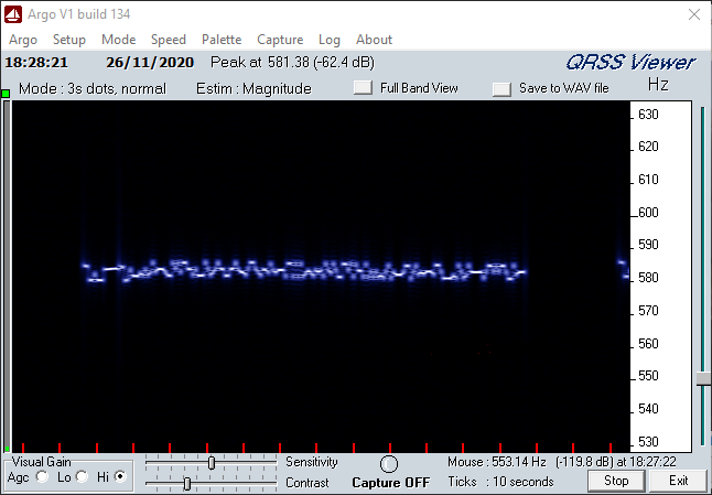
A QRSS viewer software can be used to test the beacon operation before connecting it to an antenna. An option is ARGO QRSS viewer. This test requires a HF receiver and a digital modes interface, so the audio signal can be fed into the PC’s soundcard. An example of a correct full WSPR frame that can be decoded is shown below. The critical aspect here is that the separation between the tones that are transmitted looks correct (subjectively judged, since this viewer does not have a high resolution).
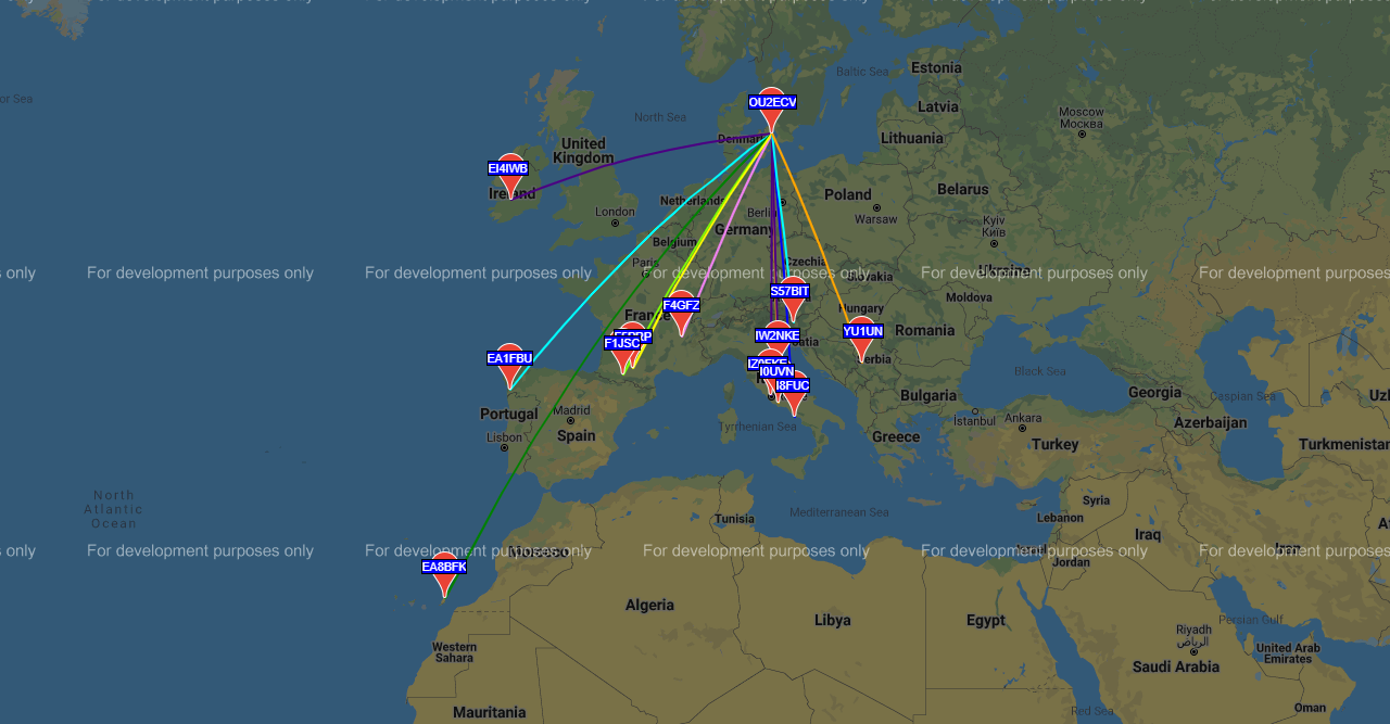
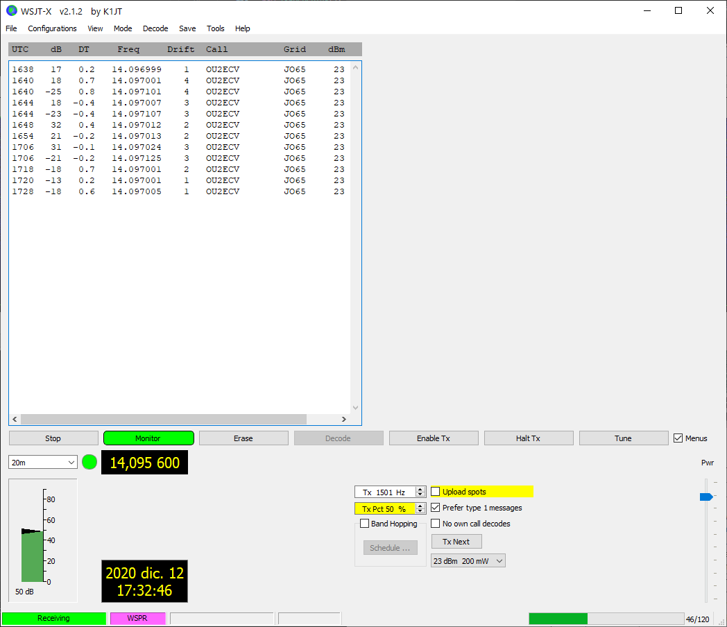
The last step is to check that data framing and beacon time sync is correct so the transmission can be be decoded. This is accomplished by transmitting while running the WSPR decoder present in WSJT-X official software. Below an example of several succesful decodifications for the message “OU2ECV JO65 23” - which indicates OU2ECV transmitting from locator JO65 (Copenhagen) with 23 dBm (200 mW).
Final words before transmitting
- The PA FET can and will get hot. Attach a heatsink/adopt the necessary precautions.
- Trasmission in amateur radio bands requires an amateur radio license. Comply with local radio and EMC regulations!
Transmission results
Many people are skeptical about the distances that can be accomplished with just 200mW of RF power. I was myself, until I built and put this radio beacon on the air. The map below shows all the stations that reported receiving my station (OU2ECV in the north of Europe), when transmitting WSPR frames at 200mW with my loop antenna inside my apartment in the 20m band.