Magnetic Loop Antenna 14-28 MHz
In this page I describe the most relevant aspects in the construction of a Magnetic Loop Antenna (MLA) designed to operate from 14 MHz to 28 MHz (20m to 10m bands). I cover antenna mechanical construction, hardware and software aspects. This is basically a compilation of design notes that I have created over this project and that I would have liked to have when I started it. It is the hope that this will encourage future builders and facilitate the construction of quality loops.
The project material is available in its github repository! There you can find the source code, hardware schematics and additional notes on hardware and software configuration.
Antenna specifications
- Maximum power rating: 100 Watts (tested)
- Bandwidth: TX 14 to 28 MHz
- Loop diameter: 88 cm
- Tuning through vacuum capacitor with electronic remote control.
- Rotation end-stop protection through absolute positioning.
Loop construction
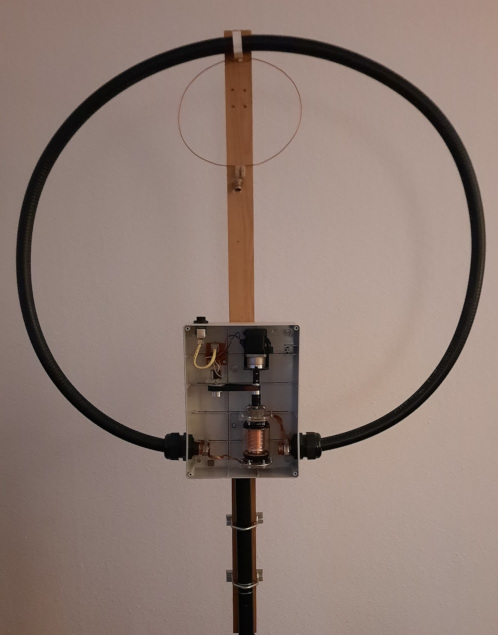
The outer loop of the antenna is made of cellflex/heliax cable (section 7/8”). The diameter of the outer loop is 88 cm (length 2.76 m). This kind of cable is used as transmission line in high-end RF installations (e.g. mobile telephony stations). The purity of the copper is much higher if compared to the material used in plumbing copper pipes. Also, construction is considerably simplified as no soldering of loop sections is required (needed when assembling the popular octogonal-shaped antennas).
The inner loop is made of thick soild copper wire and has a diameter of 19 cm. It is the weakest part of the antenna and for a more robust finishing this should be replaced by an inner loop constructed with coax cable (RG-58 will suffice).
The vertical support of the anntena is a wooden stick, here it is important to emphasize that no metallic supports shall be used to hold the antenna, as they will affect its efficiency. The attachment of the loop to the wooden support is done through a PVC gardening pipe support. The antenna is held straight through a heavy-duty tripod for camping TV-sat antennas, available on e-bay. It is bulky but light and very solid, and considerably cheaper than a photography/hi-fi tripod. The wooden support is attached to the tripod using regular metalic mounting brackets.
The tuning unit is enclosed in a plastic box used in electrical installations. The loop terminals are inserted into the box and protected with cable glands. The same strategy has been used for the control cable, with a ruggedized RJ-45 connector.
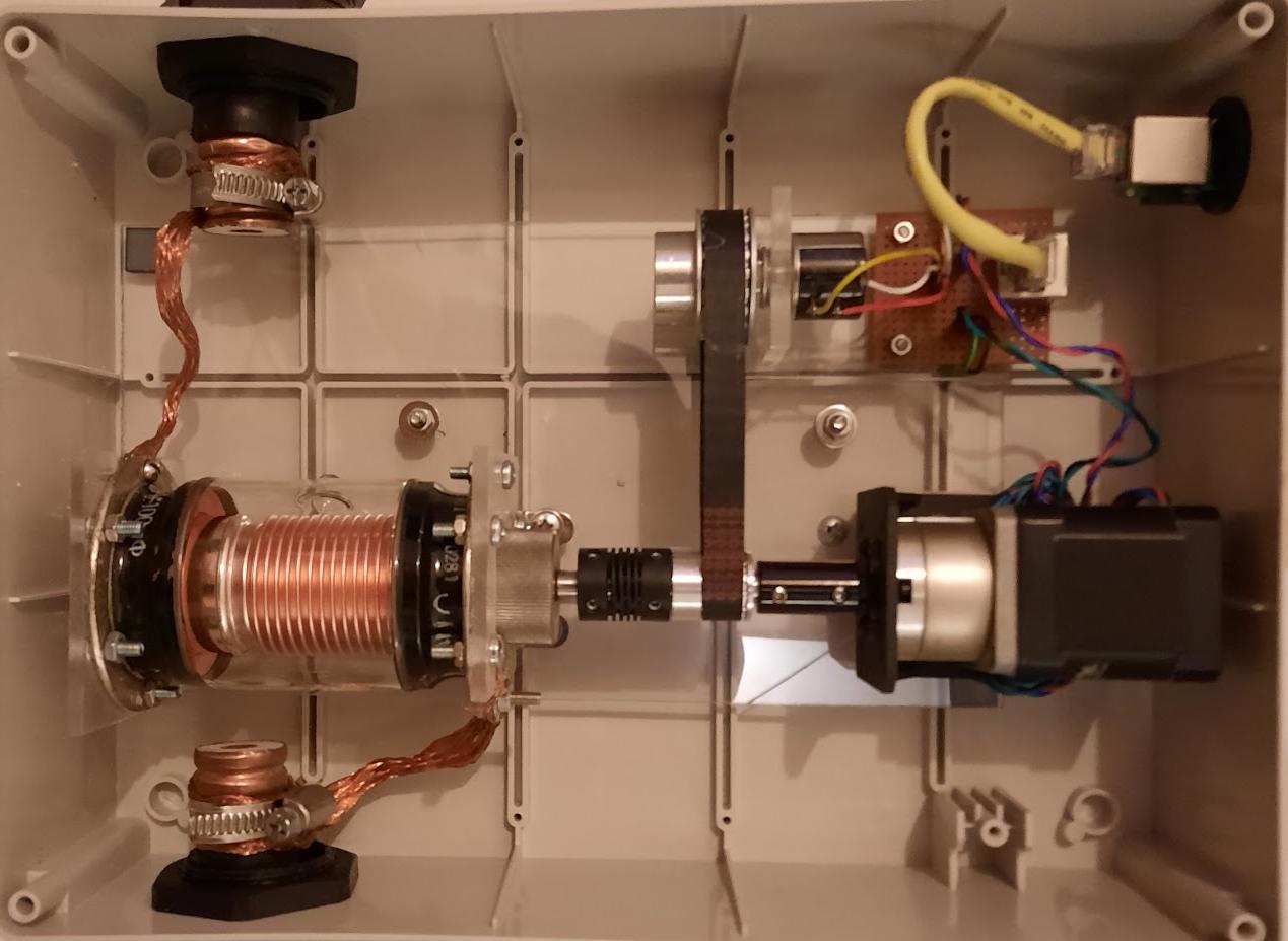
Tuning unit
The tuning unit is one of the parts where I have spent most of the design and prototyping time. The tuning capacitor is a vacuum-type soviet 100 pF capacitor of maximum rating 5 kV. A capacitor with higher capacitance could be used, resulting in a higher bandwidth. However this comes at the price of higher costs, a bigger capacitor that requires higher torque to operate and the need for a more complex support. Also, the diameter of the outer loop would prevent it from achieving a high TX efficiency in lower bands.
A multiturn potentiometer is used to determine the capacitor position. Multiturn potentiometers typically have 10 turns from minimum to maximum resistance. The vacuum capacitor used in this build has 14 turns from minimum to maximum capacitance. Rotations have to be reduced so the capacitor tuning range is not mechanically constrained by the potentiometer rotation range. To that end, a timing belt and two pulleis of different size are used, achieving a 2:1 reduction ratio.
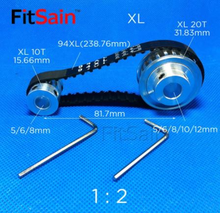
The timing belt and pulleis used are:
- Belt model 94XL, 10 mm width
- Small pulley diameter 15.66 mm, center hole 8 mm
- Big pulley diameter 31.83 mm, center hole 6 mm
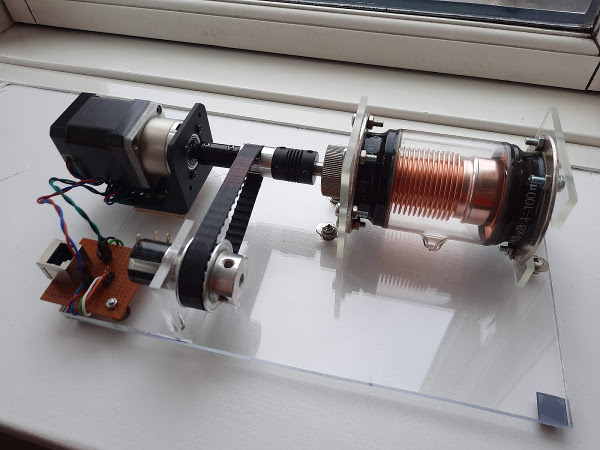
The transmission of movement between the stepper motor and the vacuum capacitor is implemented through a combination of two differnt types of couplings. It is key that there is no electrical connection between the tuning capacitor shaft and anything else. A detail of the transmission is seen in picture XX. The stepper motor shaft connects through a solid coupling to a solid aluminium shaft, where the small pulley is mounted. Following it there is a flexible plastic coupling that finally connects to the stepper motor shaft. Using a flexible coupling is, althought not required, highly recommended because it will compensate for small missalignments between the motor and the capacitor that otherwise would result in vibrations. If no suitable plastic couplings can be found, an alternative is to use a teflon shaft to connect stepper motor and vacuum capacitor. However, since these components are used in 3-d printers, they are abundant on-line.
- Select thick plexiglass (5mm at least) so it will keep the overall assemby in place, even when high torque is needed to move the capacitor. This will also help to minimize backslashing.
- Design the mounting support so there is room for final adjustment and alignment. When making the wholes in the plexiglass base, make sure they are a few mm bigger than what is needed and afterwards use washers for final assembly.
The stepper motor is a key component that has to be selected carefully for this application. Factors that are especially important are step size, power rating and reduction. In order to operate the vacuum capacitor without any external reduction, the antenna uses a NEMA 17, 200 steps/rotation with planetary reduction gear of 5:1. It gives enough torque to move the capacitor as well as a smoother rotation.
Design alternative: a NEMA17 400 steps stepper motor without planetary reduction can successfully rotate the capacitor selected. However, this comes at the cost of much higher current draw (up to 700 mA) to achieve operation towards the end of the rotation. I recommend using a stepper motor with reduction gear, that can deliver the torque required and stay within a comfortable margin of 150 mA of current at 12V in the motor windings.
The stepper motor holding bracket has to be selected so it is compatible with the stepper with planetary reduction box, meaning that it shall be possible to use holding screws within 14mm from the center shaft. See for comparison regular holding bracket and holding bracket compatible with the gearbox. Brackets compatible with steppers with gearbox are a bit less common but still possible to find at reasonable prices in eBay.
Electronic Control Unit (ECU)
The ECU is responsible for:
- Driving the stepper motor at two diffrent speeds, in clockwise and counter-clockwise directions.
- Reading the capacitor position and displaying it on the LCD screen.
- Stopping the movement of the stepper if approaching the mechanical limits.
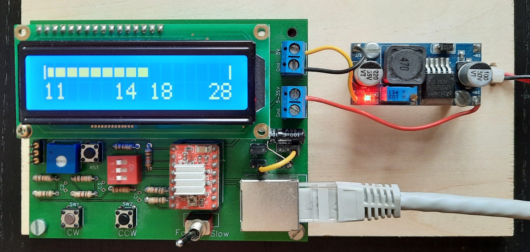
The two core components in the ECU are an arduino pro micro to run the control software and an Allegro A4988 to drive the stepper motor. The rest of the hardware components are common passives, push buttons and connectors. The PCB is a two layer board that I designed using easyEDA (free on-line CAD tool) and produced through jlcPCB. PCB designs are available in the project repository under pcb/initialPrototype.
Driving the stepper motor
Diring the stepper motor for optimal operation is a key aspect for succesful antenna usage. Speed has to be carefully determined so it is possible to change the bands fast while making it also possible to fine tune the antenna to achieve low SWR. The speed can be determined experimentally by playing with different pulse frequencies and duty cycles. Depending on target speed and selected stepper, a progressive acceleration will be needed. A function generator with TTL output can help to determine the optimal driving frequency without constant compilation/deployment/testing cycles.
In addition to speed, carefully adjusting the following aspects wil greatly improve performance:
- Microstepping will allow for smooth stepper roation. The stepper driver used in this project is configured to a 16 step reduction. This is a fixed configuration via DIP switches, but it could be programmable if desired via GPIOs.
- Disable driver when not rotating is a MUST. It avoids noise in the radio receiver and decreases current draw. Therefore, the enable line in the Allegro A4988 driver has to be toggled accordingly when the motor is not in use.
- Tune maximum current so microstepping works correctly and the motor does not exert more torque than necessary. It decreases the heat disipated in the stepper motor driver and the vibrations in the mechanical assembly.
Based on the above, the following considerations apply to this specific application:
- In this build a 200 steps stepper motor with a 1:5 gearbox is used, therefore and accounting for the microstepping configuration: 16 micro_steps/step * 200 steps/motor_rotation * 5 motor_rotation/shaft_rotation = 8000 micro_steps/shaft_rotation
- Due to the way microstepping works, if no torque is held, the position achived through microstepping will be lost. In this application this is acceptable.
WARNING: do not disconnect the motor while the driver is powered and especially if the motor is rotating or holding torque, else the driver will be damaged.
Hardware considerations
The stepper motor is operated at 12V and the rest of the electronics at 5V. To simplify how to power the control unit, 12V are supplied directly from a regulated power supply to the stepper motor driver and, from there, regulated through a small switch-mode down converter the 5V needed for the rest of the electronics. To power the whole control unit a wall adapter or the same supply used at 13.8 for radio equipment can be used
In order to use the control board with the ADC reading the absolute position sensor in the tuning unit box, a specific jumper configuration of the board is required. Additional details can be found in [hardware configuration].
IMPORTANT: The motor driver shall be disabled through reset and power-up, else unwanted steps will be triggered in the stepper motor. This is implemented through an pull-up resistor in the enable line of the driver (EN, active-low).
IMPORTANT: Apply a low-pass filter to the ADC line to avoid false end-stops. The ADC reads the multiturn-potentiometer responsible for absolute positioning. This potentiometer is connected through several meters of cable, running up to the tuning unit and together with the motor control signals. This setup is prone to pick-up electrical noise in the ADC lines, in this case the signal present is rich in harmonics between 1 to 8 kHz and modulated at 50 Hz. This is resulting in spurious triggers of the sofware end-stop protections. In order to remedy it, a hardware-based low-pass filter has been added at the ADC input.
Software considerations
The software controller can be configured to handle regular broadcasting capacitors, butterfly capacitors or vacuum capacitors. The main considerations from a software point of view are:
- Number of rotations needed to cover from minimum to maximum capacitance.
- Strategy to achieve absolution positioning.
In this case, the strategy to achive absolute positioning is direct reading of a potentiometer, which by construction keeps its value after power-off. Additionaly, by mechanical design, each position in the tuning range has a unique value. This means that it is not needed from a software point of view to keep a count of steps sent to the driver, or a number of full rotations for positioning purposes and to store them in EEPROM through power-cycles. Although both options can be activated in the software controller, relying on a hardware positioning is more robust. A complete description of the configuration options is available at [firmware configuration].
The software is structured around the following classes:
- Controller: contains the entry point, instantiates and initializes the system in the
setup()function and callsmode->execute(). - Mode: is the base class that allows access to the hardware drivers and contains the common definition of how the motor should be driven in the
operateMotor()function. - Mode operate encoder: is the sepecialized version of
Modeimplementing system operation using rotation limits based on encoder reads. - Mode operate: displayed for completenes but not used. This is a specialized version of
Moderelying counting the number of pulses sent to the stepper to keep track of position. - Hardware access classes: encapsulate the access to the hardware peripherals. Implemented as singletons.
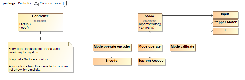
In this controller the mode class that is used is an instance of Mode operate encoder, which implements the execute() function as presented in the listing below. This function will periodically read user inputs, read the position of the encoder and check if the movement can be allowed and operate the motor accordingly. In case the motor has moved the refreshcount in the display class will be incremented. This internal count will trigger a LCD display update when a certain limit has been reached. The purpose with this is to affect the motor rotation as little as possible. In case the motor is not moving, the display will be updated immediately.
virtual void execute() {
  moved = false;
  userInput->readInputs();
  display->update(getCount());

  if (checkLimits()) {
    moved = operateMotor(userInput->getSpeed(), userInput->isRotateCW(),
      userInput->isRotateCCW());
  }

  if (moved) {
    display->updateRefreshCount();
  } else {
    display->updateImmediate();
  }
}
The motor is moved through the operateMotor function, which handles interaction with the stepper driver. In case the motor is going to be moving in clockwise (CW) or counter-clockwise (CCW) directions, the driver is enabled and the rotation direction set accordingly. If the motor is not going to rotate the driver remains disabled to reduce current draw. Finally, a delay is inserted depending on the speed, so the separation between pulses triggering steps vary accordingly.
uint8_t operateMotor(uint8_t speed, uint8_t CW, uint8_t CCW) {
  uint8_t motorMoved = false;
  stepper->setSpeed(speed);

  if (CW) {
    stepper->enableMotor();
    stepper->rotateCW();
    motorMoved = true;
  } else if (CCW) {
    stepper->enableMotor();
    stepper->rotateCCW();
    motorMoved = true;
  } else {
    stepper->disableMotor();
    motorMoved = false;
  }

  if (speed == SLOW) {
    delay(OPERATION_DELAY_SLOW);
  } else {
    delay(OPERATION_DELAY_FAST);
  }

  return motorMoved;
}
The execution of operateMotor is conditional to the result of checkLimits. The movement is only allowed if the physical limit detected by the encoder has not been reached. If it has, the movement would only be permitted in the unconstrained direction, where the axis can rotate.
bool checkLimits() {
  bool isWithinLimits = false;
  if (userInput->isRotateCW()) {
    isWithinLimits = ((getCount() > limitMin) ? true : false);
  } else if (userInput->isRotateCCW()) {
      isWithinLimits = ((getCount() < limitMax) ? true : false);
  }
  return isWithinLimits;
}
Build vs. buy
A commercial loop antenna (MFJ 1786X), covering from 10 to 30 MHz costs around 600 Euros including shipping from a European dealer. This model comes with a tunner box and a ruggedized finish and is ready to mount outdoors. Looking at the costs of the material I used in this prototype, I have spent roughly 200 Euros for the antenna and tunning unit and around 40 Euros in prototyping. I have lost track of the time I have spent building and experimenting (one could claim that time also has a cost).
If I factor in all the spare material that I have acquiered previously to experiment with other loop configurations and different kinds of capacitors, costs will probably be on pair or above with buying a new, ready made, antenna. So, from a cost-savings perspective, the savings have been non-existent. However, I have learnt on the way and enjoyed the process, and that is what matters!
References
- Component datasheets link
- “An overview of the underestimated magnetic loop antennas” link
- A number of DIY Builds that I have gotteng insperation from: the archive -> radio -> magnetic loop articles link
Bill of Materials
- 100pF vacuum capacitor
- Stepper motor with planetary reduction 5:1 - 17HS15-1684S-PG5
- Cellflex/Heliax cable for the outer loop 3m (trim down as needed)
- Copper wire/RG58 coax cable for the inner loop 60 cm (trim down as needed)
- Aluminium shaft, flexible and rigid couplings
- Belt model 94XL, 10 mm width
- Small pulley diameter 15.66 mm, center hole 8 mm
- Big pulley diameter 31.83 mm, center hole 6 mm
- 10 kOhm multiturn potentiometer
- Stepper motor holding bracket
- Vertical wooden support
- Two commercial antenna mounting brackets
- Plexiglass sheet
- PVC electricity box
- 2 x Cable glands that fit a 7/8” cable.
- Garden hose clamps
- Assorted screws, nuts and bolts
- RF connectors: PL-239 in this case - configure as needed.
- Rj45 ruggedized connector