A lightweight coaxial magnetic loop antenna for QRP
Notes on the construction of my portable magnetic loop for QRP operation.
A coaxial cable-based magnetic loop is an excellent starting point to experiment and get familiar with the working principles of magnetic loop antennas. Magnetic loops perform well in RX and, when designed and built correctly, will yield contacts across different bands and modes. In this page I describe the most relevant details of my QRP portable loop.
Main characteristics of this antenna:
- Resonant from 7 to 28 MHz.
- Will widthstand a maximum power 15 Watts
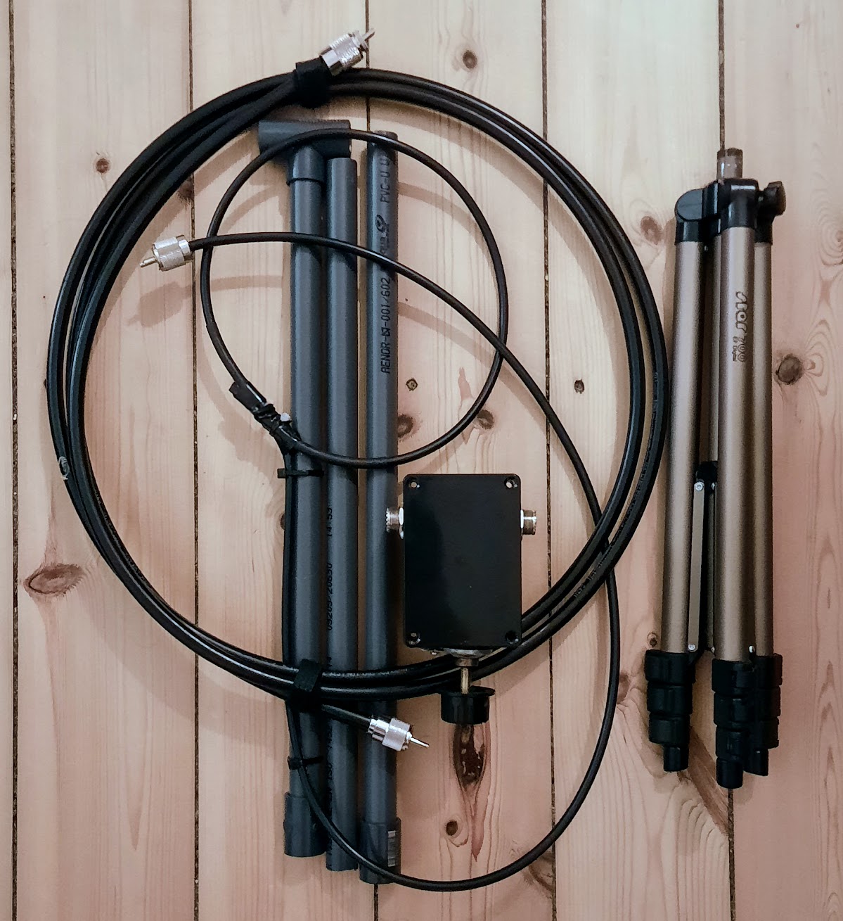
- 1 meter diameter outer loop, made of coaxial cable LMR400. 1 cm cable section.
- Vertical support made from PVC tubing, collapsable in three sections and mountable in a photography tripod.
- Cost below 50 USD/Euros

|
|
Construction notes
Content distrilled to the bare minimum and focused on the critical aspects and most common pitfalls. To be read carefully by future builders. If you follow the instructions presented here your antenna will work.
Outer and inner loops
The outer loop of this antenna is made from 3.14m coaxial cable LMR400. Thanks to its rigidity, the cable will hold the ciruclar shape better than other more flexible cables like RG213. When mounting the loop, the inner conductor and the jacket shall be shorted for efficiency reasons. I have done this in the female connectors instead of in the cable itself or the male connectors. This is a safety measure, in case I reuse the outer loop at a later point as a transmission line. The inner loop needs to have a legth of 1/5 and 1/8 of the outer loop, as in any normal magnetic loop construction. In this antenna, the inner loop has a diameter of 20 cm. The inner loop has to be very close to the outer one in order to achieve a low SWR. Many builders cannot achieve low SWR values due to incorrect positioning of the inner loop. The inner loop is made from RG-58 coaxial cable, where the braid has been shorted to the core.
Finally, the transmitting loop is kept in many builds with a vertical piece of PVC tubing, this is simple and has a low cost. Others also use coaxial cable for the vertical support (see for example the CHA F-LOOP). As it is best to use a material that is not metallic to avoid losses and with the aim of keeping it simple I used PVC piping.
Capacitors
The loop is tuned through a broadcasting type, variable capacitor1. Sections are connected to the female UHF connectors as shown in the pictures below. If your capacitor has trimmers, open them fully so the capacitor can achieve its minimal capacitance, and therefore being able to tune the highest bands.
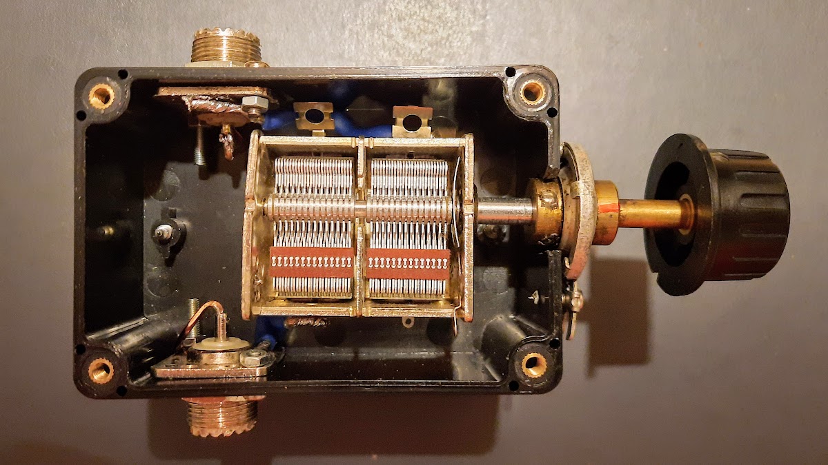
There is a planetary redution gear2 coupled to the capacitor shaft. This is advisable so it is easier to tune the loop, otherwise it is difficult to find the spot where SWR is the lowest. Electrical tape has been placed around the shaft so there is no connection between the capacitor and the planetary reduction. Finally, a plastic knob has been placed on the outer shaft used to rotate the capacitor.
Electrical isolation is a requirement since one should not touch the capacitor shaft when tuning the antenna. This is due to the “hand effect”, which will affect the tuning capacitance. Furthermore, if the antenna is in TX while touching an un-isolated shaft, one can get an RF burn even at low power levels due to the high voltage developed in the outer loop.
Theoretical calculations
These are the calculations for an antenna with an 1 m diameter outer loop, made from an outer loop cable of 1 cm section and 1 m diameter.
| 7 MHz | 10 MHz | 14 MHz | 18 MHz | 21 MHz | 24 MHz | 28 MHz | |
|---|---|---|---|---|---|---|---|
| Efficiency | 7% | 21% | 46% | 67% | 78% | 85% | 91% |
| Bandwidth | 13.4 kHz | 18.8 kHz | 32.6 kHz | 61 kHz | 97.7 kHz | 152 kHz | 265 kHz |
| Tuning capacitance | 293 pF | 144 pF | 73 pF | 44 pF | 33pF | 25 pF | 18 pF |
| Capacitory Voltage [RMS] @ 100 Watts | 2013 V | 2472 V | 2579 V | 2424 V | 2236 V | 2043 V | 1809 V |
| Circulating current @ 100 Watts | 26 A | 21.9 A | 16.6 A | 12.2 A | 9.62A | 7.69 A | 5.83 A |
| Capacitor Voltage [RMS] @ 5 Watts | 450 V | 543 V | 577 V | 542 V | 500 V | 457 V | 404 V |
| Circulating current @ 5 Watts | 5.81 A | 4.90 A | 3.72 A | 2.72 A | 2.15 A | 1.72 A | 1.30 A |
Comments:
- Radiation efficiency is higher with thicker outer loops (e.g. 2 cm, 7/8” heliax/cellflex).
- Capacitor plate separation does not make it possible to operate at high power due to the voltage developed in the tuning capacitor.
- These calculations are orientative. When implementing the antenna there are factors that will make real measurements deviate from the theoretical calculations (e.g. resistive losses, distributed capacitance).
Other loop antennas, commercial and homemade. …and the build vs. buy dilemma.
I started experimenting with magnetic loops in 2012 after reading G4ILO article on his “wonder loop”. It is a very comprehensive article that I recommend reading. A second homemade build that I specially liked was YOGGX Portable remote tunable magnetic loop antenna. The article describes a simple way to tune the capacitor through a RC-servo.
This is an antenna that every loop experimenter should build however, purchase of a commercial model shall be carefully considered. One shoud not forget that in the end one will be paying for a capacitor in a box and a piece of coaxial cable. Nevertheless, at this point of my life and considering the time I have at my disposal, I would be inclined to buy the OM0ET Ultralight MLA MC 20. The reasons being: it is reasonably priced and the creator has a complete youtube channel detailing its construction (among other contents). There are other models in the market besides these two antennas however, since their retail prices in Europe are between 500 to 600 Euros, it is not reasonable to consider their purchase (as I said, it is a capacitor in a box and a cable).
Final comments
Many builders/users of this types of magnetic loops praise their lower susceptibility to electrical noise, resulting in improved RX capabilities. Unfortunatelly there is just too much RFI and non-compliant electrical appliances in the average household. The magnetic properties will help to a certain degree. The null in its radiation pattern is indeed a reality, but very often you will have to choose between nulling the offending RFI or maximizing the rx level of the target signal.
This is a simple yet effective antenna. I have used it both portable and in my apartment balcony extensively and with good results. You will not be able to do DX work daily, but it will get you in the air. The antenna will yield contacts even when operated indoors, especially when using digital modes or CW.
Notes
-
Butterfly capacitors are a better choicie but its availability is limited, they are more expensive and bigger in size. ↩︎
-
Vernier dials are also a good option to implement the reduction, but it might be difficult to find a high quality one. Good material is available at orenlliotproducts and mainline-group. ↩︎